Manual
The beam pump is comprised of a standing valve at the bottom of the well, and a traveling valve attached to a rod that moves up and down the well driven by a motorized horse-head assembly on the surface, see figure 1.
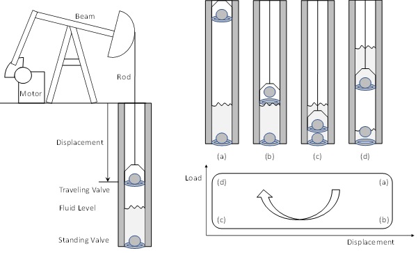
Figure 1.
Diagram of a beam pump.The journey of the traveling valve from the top of the well to the bottom and back up again is called a stroke. As the pump returns to the same configuration at the start of every stroke (unless the pump breaks), the motion is inherent periodic. When the rod starts its downward journey, the standing valve closes; figure 1(a). The traveling valve opens as soon as it encounters fluid in the well and allows it to pass through; figure 1(b). At the bottom of the stroke, the traveling valve closes, and the journey is reversed at which point the standing valve opens again allowing fluid to enter the well; figure 1(c). As the closed traveling valve moves up, it transports the fluid it collected during the down-stroke to the surface; figure 1(d). We can measure both the load, i.e. the weight of the fluid above the traveling valve, and the displacement from the surface during one full stroke. If we graph these two variables against each other, we get a diagram known as a dynamometer card; see figure 1 bottom-right and compare with figure 2 for a real example.
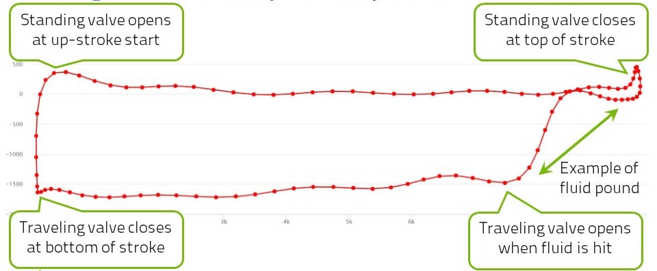
Figure 2.
Sample dynamometer card with the four main events during a pump stroke indicated.It was discovered by Walton Gilbert in 1936 that the shape of the dynamometer card allows an experienced person to diagnose precisely any of the typical problems that a beam pump can have downhole. It is difficult to measure the load on the moving rod directly and so we measure it at the top of the rod and infer the downhole conditions by solving the wave equation. Based on this we can calculate several physical quantities such as a pump intake pressure without measuring them [17] and use the computed downhole card effectively to diagnose problems with the beam pump [14]. This method of determining the dynamometer card (measure at the top of the well and compute the downhole conditions) is now industry standard and relies on accurately approximating the friction laws that the moving parts experience on their journey.
This diagnosis is here done by computer, automatically.
This is how the computerized method works:
- The wells in our oilfield are listed.
- The categories into which the dyna cards are to be classified are listed.
- Historical dyna cards from the wells are acquired and some are manually labeled.
- Models are created, trained on manually labeled data, and then applied to the historical data.
- The results can now be checked for all categories and we may judge the accuracy of the model.
- The current status of all wells can be checked in a hierarchial fashion.